Creating Your First Blueprint
It is completely normal to feel overwhelmed when you first open the node editor. There are so many nodes, and so many things you can do with them! But don't worry, we will walk you through the basics of blueprints in this section.
Your First Blueprint
Let's start with a simple example. Suppose you want to shake the camera when the Esc key is pressed. First, click the Add Blueprint button in the toolbar to add a new blueprint. You can optionally rename the blueprint to something more meaningful, e.g., "Shake Camera On Esc", but we can leave it for now.
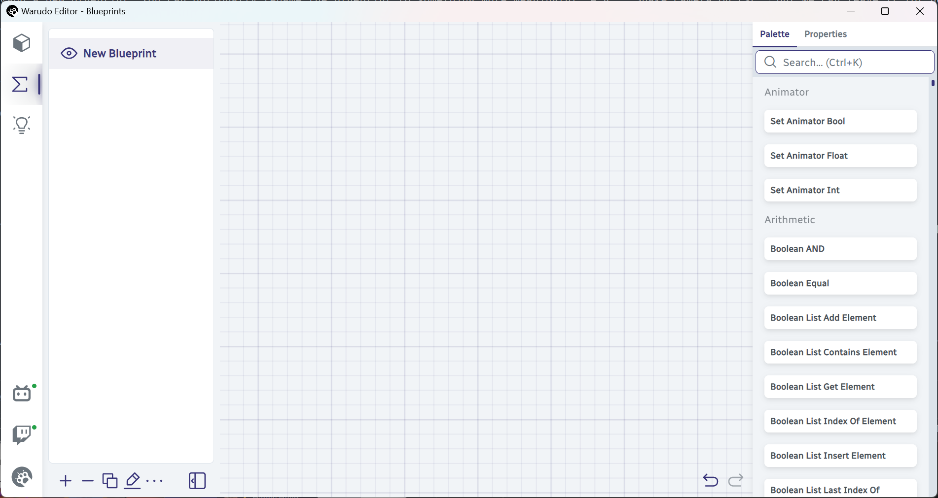
Adding a new blueprint.
This is a beautiful blueprint, but it is also completely useless. We need to add some nodes to it. Type "on keystroke" in the search bar, and you should see the On Keystroke Pressed node. Drag it to the node editor, and you should see something like this:
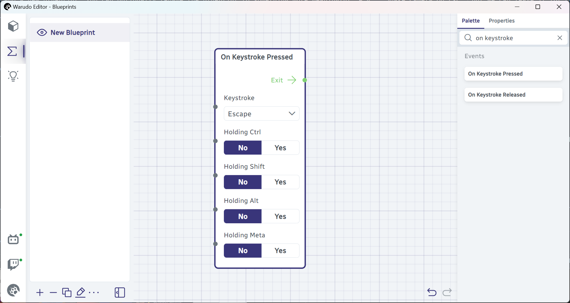
Adding the On Keystroke Pressed node.
If you have accidentally dragged the wrong node, you can click to select the node and press Delete to delete it. Alternatively, you can also use the Undo button.
Awesome! Now, we need to add a node that shakes the camera. Type "shake camera" in the search bar, and you should see the Shake Camera node. Drag it next to the On Keystroke Pressed node, and here's a challenge for you: try to connect the On Keystroke Pressed node to the Shake Camera node like below.

Adding the Shake Camera node and connecting it to the On Keystroke Pressed node.
If you clicked on the green dot next to the Exit on the On Keystroke Pressed node and dragged it to the green dot next to the Enter on the Shake Camera node, congratulations! You have great intuition. By the way, you can remove the connection by clicking on either end of the connection and dragging it away.
The green dots on the right side of a node are called flow outputs, while the green dots on the left side of a node are called flow inputs. So, you just connected the Exit flow output of the On Keystroke Pressed node to the Enter flow input of the Shake Camera node.
A flow connection determines the order in which the nodes are triggered. In this example, we are saying that when the On Keystroke Pressed node is triggered, the Shake Camera node should be triggered next.
We are done, right? Let's try to press the Esc key and see if the camera shakes.
Huh, the camera didn't shake at all. I wonder why?
Let's take a closer look at the Shake Camera node. It has a Camera data input, but it is not set to anything! Let's select our camera from the dropdown:

Setting the Camera data input.
Let's try to press the Esc key again. If the camera shakes, congratulations! You have successfully created your first blueprint.
Passing Data Between Nodes
Now, you may wonder what are these black dots next to the data inputs on the Shake Camera node. Indeed, they look suspiciously similar to the green dots next to the Enter flow input. Maybe they can also be connected to something?
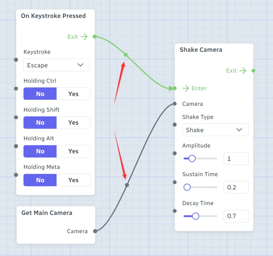
Indeed, they can! Let's drag a Get Main Camera node from the node palette to the node editor, click the black dot next to the Camera data output of the Get Main Camera node, and drag it to the black dot next to the Camera data input of the Shake Camera node, like this:

Connecting the Get Main Camera node to the Shake Camera node.
Recall that Warudo supports multiple cameras, and the main camera is the camera that is currently shown in the main window.
Try pressing the Esc key again. Hey, the camera still shakes! But this time, note that the Camera dropdown has disappeared. It means that the Shake Camera node is taking the camera from the Get Main Camera node instead, and the camera we selected from the dropdown is ignored (though technically they are the same camera anyway).
Let's create another camera in the Assets tab, switch to that camera, and then press the Esc key again. You will note that the new camera is the one that shakes, not the one we selected from the dropdown!
Similar to flow inputs/outputs, the black dots on the right side of a node are called data outputs, while the black dots on the left side of a node are called data inputs. So, you just connected the Camera data output of the Get Main Camera node to the Camera data input of the Shake Camera node.
A data connection is responsible for passing data between nodes. In this example, we are saying that the Camera data input of the Shake Camera node should be set to the Camera data output of the Get Main Camera node, when the Shake Camera node is triggered.
Now, even though this is just a toy example, this is what creating a blueprint is all about: find the nodes that we need and connect them together, so that we can tell Warudo what to do (shake camera) when something happens (pressing Esc).
Let's summarize what we have learned so far:
-
A blueprint consists of nodes and connections. Connections come in two types: flow connections and data connections, while each node can have both flow and data inputs and outputs. A data input can be either set directly on the node, or connected to a data output of another node.
-
To create a connection, click on the input/output port and then drag it to another node's output/input. Flow connections determine the order in which the nodes are triggered, from left to right. Data connections are responsible for passing data between nodes, also from left to right.
A flow input can connect to multiple flow outputs, but a flow output can only connect to one flow input. Otherwise, it would be unclear which node should be triggered first.
Similarly, a data output can connect to multiple data inputs, but a data input can only connect to one data output. Otherwise, it would be unclear from which node the data should be passed.
Feeling a bit overwhelmed? Don't worry, we will go through many more examples in the following sections.
Data Types
As a side note, the data types of the two ends of a data connection must be compatible. In the example above, you cannot connect Get Main Camera → Camera (data type: camera asset) to Shake Camera → Sustain Time (data type: "float," the fancy way of saying a decimal number). You can hover on the port to see its data type:

Hovering on a port to see its data type.
Most of the time you don't need to worry about data types, because we all know a camera can't be a number!
Disabling Blueprints
A blueprint can be disabled by clicking the eye icon next to the blueprint name. When a blueprint is disabled, the nodes in the blueprint will not receive events. For example, in the example above, if the Esc key is pressed when the blueprint is disabled, the On Keystroke Pressed node will not receive an event and the flow will not be triggered, and as a result the camera will not shake.
You can determine if a flow is being triggered or if data is being passed by checking if there's a ball rolling on the connection:
Authors